
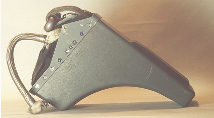
 The drogue gun was designed with a simple
clockwork to fire after a second or two of delay from first seat
motion to allow the seat to clear the structure
and make sure the drogue could be launched into clear air.
After that delay the drogue gun fires a slug of metal that weighs about one
pound into the air with a cartridge similar to a 12 gauge blank. This
physically, and violently rips the drogue chute from its
pack in the headrest
in front of the main beams. The drogue chute inflates rapidly and slows the
seats forward motion, while stabilizing it vertically. Once the TRM
functions (see below), the drogue shackle which is attatched to the drogue
chute linesis freed and pulls the main chute extraction line. This line
has attatchment points on both sides of the headrest which pull out a
pair of clips (visible in the pictures of the TRM). These
clips release the face curtain and the parachute box retaining lines. Then
the chute extraction line pulls out the main chute rip cord pins allowing
the pack opening spring to force the flaps of the parachute box open and
launch the parachute out to inflate. The drag from the parachute
overcomes the friction of the rest of the connections between the
crewmember and the seat (all the 'hard' connections are released by the
TRM as described below) and pulls the crewmember off the seat. Parts
such as the parachute container box, the face curtain and overhead
handle, and the parachute box retaining straps, as well as the seat
itself continue on their merry way towards the ground.
The drogue gun was designed with a simple
clockwork to fire after a second or two of delay from first seat
motion to allow the seat to clear the structure
and make sure the drogue could be launched into clear air.
After that delay the drogue gun fires a slug of metal that weighs about one
pound into the air with a cartridge similar to a 12 gauge blank. This
physically, and violently rips the drogue chute from its
pack in the headrest
in front of the main beams. The drogue chute inflates rapidly and slows the
seats forward motion, while stabilizing it vertically. Once the TRM
functions (see below), the drogue shackle which is attatched to the drogue
chute linesis freed and pulls the main chute extraction line. This line
has attatchment points on both sides of the headrest which pull out a
pair of clips (visible in the pictures of the TRM). These
clips release the face curtain and the parachute box retaining lines. Then
the chute extraction line pulls out the main chute rip cord pins allowing
the pack opening spring to force the flaps of the parachute box open and
launch the parachute out to inflate. The drag from the parachute
overcomes the friction of the rest of the connections between the
crewmember and the seat (all the 'hard' connections are released by the
TRM as described below) and pulls the crewmember off the seat. Parts
such as the parachute container box, the face curtain and overhead
handle, and the parachute box retaining straps, as well as the seat
itself continue on their merry way towards the ground.
Time Release Mechanism
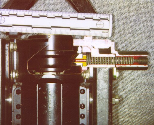
Catapult
The diagram on the left shows the basic function of the catapult and 80 foot
per second gun. Catapult initiation is by pulling either the face curtain
primary ejection handle, or the secondary ejection handle on the front center
of the seat pan. Both handles on seats of this vintage cause the catapult
sear to be withdrawn from the top of the catapult gun (which is also the
mount that connects the seat to the cockpit. The catapult is bolted to
the bulkhead of the cockpit and is made of three concentric tubes. The
outer tube is outfitted with a set of rails which mate with six {three
on each side} slides on the inner sides of the main beam assembly. The
seat is fixed in place by the top latch which is the arrow shaped
device on the top left side * of the main
beam assembly. The top latch
is equipped with an internal indicator which when
the latch is set properly appears as a flush central dot on the outside
of the top latch. The top latch must be seated firmly in place and all
three surfaces {the top latch housing, the top latch, and the top
latch indicator} being flush with each other for the seat to be
safely in the aircraft). In this position, the top latch is inserted
through the top latch window
on the outer tube of the catapult assembly and into a
'V'-shaped groove in the breech
assembly which is attatched to the innermost piston tube of the assembly.
The cartridge in the breech at the top of the catapult then ignites and
sends rapidly expanding gas (red) down the
tube. When the gas pressure is enough, the inner and middle tubes are
forced up the assembly by the pressure and jump over the spring mounted
top latch. They then apply force to the main beam assembly and begin the
movement of the seat up the rails. The beginning of the seat movement
withdraws the sears from the TRM and
Drogue Gun by trip rods that are
mounted to the bulkhead of the cockpit.
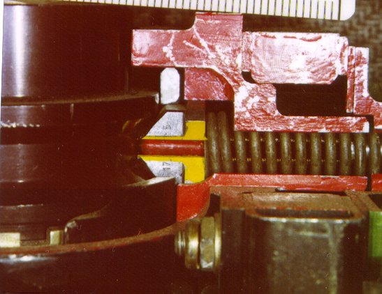
Seals on the base of the middle tube prevent the gas from traveling
up the area between the tubes. Once the middle tube has moved up the
outer tube to the point where the 'pancake charge' (one of the mounts
for the pancake charges is visible to the bottom rear of the picture
of the TRM) or charges are uncovered. At that point
the pancake charges are exposed to the hot gas and ignite. The gas
produced (yellow) increases the pressure in the tubes and accellerates
the telescoping of the tubes (and the speed of the seat itself). This
is done this way to allow a higher speed on ejection without subjecting
the seat occupant to excessive Gz. The staggered pulses of the charges
therefore are less likely to cause injury to the pilots back (if he is
seated properly. In later seats, the inertia reel attatched to the
shoulder harness is powered by a cartridge and
pulls the pilot upright prior to the seats initial movement.).
Once the middle tube is fully extended, a group of compression rings
are crushed to slow it down and prevent it from
continuing upward as the inner tube begins to extend. This tube is free to
separate from the other two tubes and continues on with the seat.
The seat/man package then continues as described above.
Leg Restraints
Mentioned earlier in passing was the leg restraint system. This consists of
three major pieces:
Manual Override
The Manual Override handle on the right hand side of the seat pan is used
in two primary cases. The most common is in the case of an emergency
evacuation of the cockpit. When the crewman is strapped to the seat by the
lower restraint harness and the upper harness Koch fittings as well as
the leg restraints it might take too much time to undo the connectors
during a ground emergency. In that case, the crewman would squeeze the
handle and raise it to the up and locked position. This accomplishes two
things. First it mechanically (via linkages) releases the leg restraints,
the survival kit, and the inertia reel. Second, but in the same motion, it
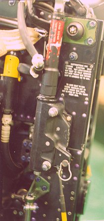
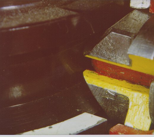
withdraws the sear from the gullitine (yes, like the French gullitine)
cartridge. This cartridge fires, and by means of a tube vectors hot,
expanding gas up to a piston on the upper left side of the seat. This
piston has a blade on it that cuts the parachute withdrawal line. The
gullitine is the cylinder with the yellow guard over the cutting area
forward of the drogue gun. The parachute withdrawal line is what connects
the drogue shackle to the main parachute, and pulls it free during seat
separation. Once these actions are complete (which takes little more than
the time to raise that handle), the crewman stands up and exits the cockpit
as rapidly as possible. Attatched to the crewman by his harness and the lap
belt are the parachute box, and survival kit (undeployed). These would tend
to limit the crewman's mobility slightly, but in an emergency situation
would likely go virually unnoticed.
The second primary scenerio is if the crewman feels for any reason that the
seat separation has failed to function, to provide a means for the crewman
to manually separate from the seat and deploy his chute. This is accomplished
as in the previous paragraph, except when the handle is lifted up, the
crewman would push himself away from the seat structure, and pull the ripcord
to actuate the secondary parachute deployment method. The parachute is
normally pulled out of the pack by means of the drogue chute, which pulls the
withdrawal line to release the ripcord pins, and then pulls the parachute in
its deployment bag out until the chute lines stretch fully, where
the drogue continues to pull the bag off the chute for a controlled
deployment. In this case, the rip cord handle pulls the pack locking pins out,
and the pack opening spring forces the pack flaps open. The opening spring
pulls out a separate parachute drogue which deploys the parachute in the
same fashion as the seat drogue, only with slightly less force.
Overview
The actions of an ejection seat are many and varied. In the Martin-Baker
system described here the functions are mechanically activated, although
some of them use cartridges to increase the reliability and force involved.
The different devices are designed to operate individually and there is a
manual backup system for the primary failure modes. Failures of either the
drogue gun, or TRM can be handled by the manual separation mode, if the
crewman acts in time. There is no substitution for a thourough understanding
of all the parts of a seat and their intended function. In the rare case that
you, the reader, would have to use one of these seats (and in saying rare, I
include the crewmembers who fly planes with these seats), make sure you have
understood the principles of the mechanics. These seats will save your life,
if you give them the chance to. That means -
Note: The cutaway pictures of the top latch assembly were taken from the
front of the seat, leading to them being backwards to the left-right
reference. The reference of a seat is based upon sitting in it. The
left of a seat would be at your left hand, and the right at your right.
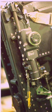
 The Time Release Mechanism (TRM)
was designed to do several functions in two simple co-joined
motions. It also functions with a basic clock mechanism that also has a
short delay initiated by a trip rod attached to the cockpit bulkhead
second delay in it. This timer can be delayed by two possible mechanisms.
One is a simple weight and spring mechanism that prevents it from
functioning while the seat is decellerating too rapidly. In other
words in a high speed ejection the timer delays activation for a
fraction of time while the seat slows slightly. Then the barostat
inhibiter comes into play. The barostat is mounted on the side of
the unit and by pressure differential determines
if the seat is above a preset altitude such as 10000 feet.
This is to prevent seat separation (and in
the earlier seats- separation from the seat mounted Oxygen system) to
allow the crewmember to descend to a warm, thicker atmosphere. Then the
clockwork timer begins to tick. (Note: the animated GIF has a short
delay imposed so that the drogue gun is fired first, then the TRM activates.)
Upon its expiration, strong springs drive a rod
in the downward direction. The top portion (black in the accompaning
diagram above right) retracts to release a 'scissor shackle' which releases the
drogue shackle and allows it to do its job.
The lower end drives downward and releases by means of a torque tube the
inertial reel harness. It also by a set of turnbuckle like links on the
torque tube releases the seat kit and harness connections for the lap belt
as well as the leg restraints.
The Time Release Mechanism (TRM)
was designed to do several functions in two simple co-joined
motions. It also functions with a basic clock mechanism that also has a
short delay initiated by a trip rod attached to the cockpit bulkhead
second delay in it. This timer can be delayed by two possible mechanisms.
One is a simple weight and spring mechanism that prevents it from
functioning while the seat is decellerating too rapidly. In other
words in a high speed ejection the timer delays activation for a
fraction of time while the seat slows slightly. Then the barostat
inhibiter comes into play. The barostat is mounted on the side of
the unit and by pressure differential determines
if the seat is above a preset altitude such as 10000 feet.
This is to prevent seat separation (and in
the earlier seats- separation from the seat mounted Oxygen system) to
allow the crewmember to descend to a warm, thicker atmosphere. Then the
clockwork timer begins to tick. (Note: the animated GIF has a short
delay imposed so that the drogue gun is fired first, then the TRM activates.)
Upon its expiration, strong springs drive a rod
in the downward direction. The top portion (black in the accompaning
diagram above right) retracts to release a 'scissor shackle' which releases the
drogue shackle and allows it to do its job.
The lower end drives downward and releases by means of a torque tube the
inertial reel harness. It also by a set of turnbuckle like links on the
torque tube releases the seat kit and harness connections for the lap belt
as well as the leg restraints.
As the seat rises up the rails, the crewman's legs under
acceleration naturally rotate about the knee to position the legs in front of
the seat bucket
On the continued ascent the leg restraint lines tighten holding the
legs in this restrained position by means of a snubber unit which prevent the
lines becoming slack. The pins in the breakaway links are sheared once the
lines reach the full extent of their travel. The leg restraints keep the legs
from flailing in the wind
blast of a high speed ejection. When the TRM actuates the torque link
in the seat bucket , the leg line release latches are operated, allowing
the leg restraint cones to detach and the leg lines
to slip free of the garters and let the crewman separate from the
seat.
