The Ejection Site
F-104G Martin-Baker Aircraft Mk. GQ-7(A)
 These photos of Mark Schimmer's GQ-7A show it to be a different version from the one shown on this page. Among the differences are the color of the main parachute box, and the headrest shape. These pictures clearly show the shape of the parachute box which wraps around the main beam assembly to flatten the side of the seat. The yellow tape running around the seat is the flag which connects all the safing pins installed on the seat.
The GQ-7A is one of the most interesting of the Mk. 7 family of Martin-Baker seats. The seat design was dictated by the narrow confines of the F-104 cockpit. The need to keep the original seat rails led to the Martin-Baker seat being somewhat forward of the normal seat position so the thickness of the seat was a major concern. This was addressed by the design of a new parachute container box which was designed to wrap around the main beam assembly to provide a thinner profile. The headrest design was changed as well to flatten it somewhat, which dictated changes to the shape and size of the drogue parachute container.
Most of the rest of the mechanisms were retained with little modification. One exception was the emergency oxygen systems. The oxygen bottle is mounted on the side of the seat bucket and connected to the European style Personal Equipment Connector (PEC) system. The GQ-7A came with more than one version of this, one of which included dual oxygen bottles for higher altitude use.
The photos below are described to show the major points of interest.
Other photos of GQ-7A seats can be found:
- Photos of a service seat at an airshow here.
- Photos of a display of a GQ-7A 'ejecting' here.
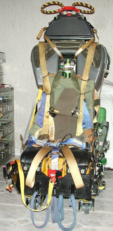
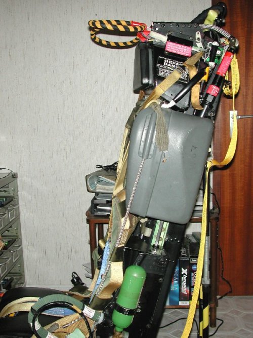
Front view Note the parachute withdrawal line
is disconnected and hanging on the right of the picture |
|
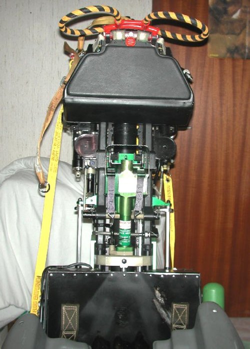
Upper back view Shows the TRM and DGU lower sections
in relationship to the main parachute pack |
|
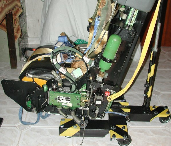
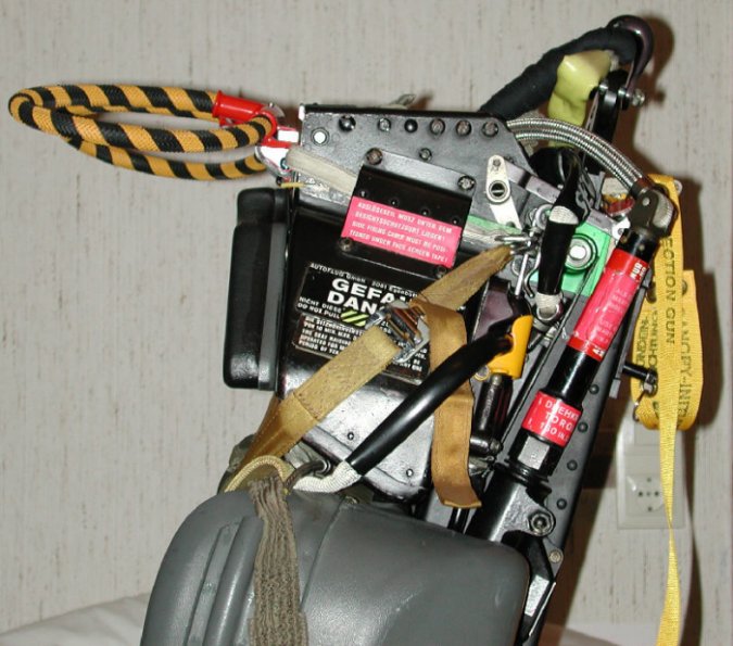
| Lower Left side view The Personal Equipment Connector (PEC) is complete with the seat and aircraft sections. |
|
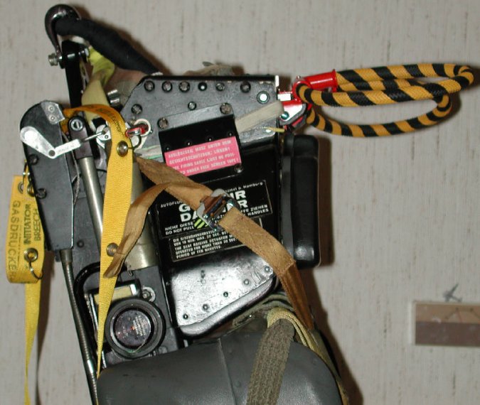
Upper Left View Clearly shows the parachute box
wrapping around the main beam assy. |
|
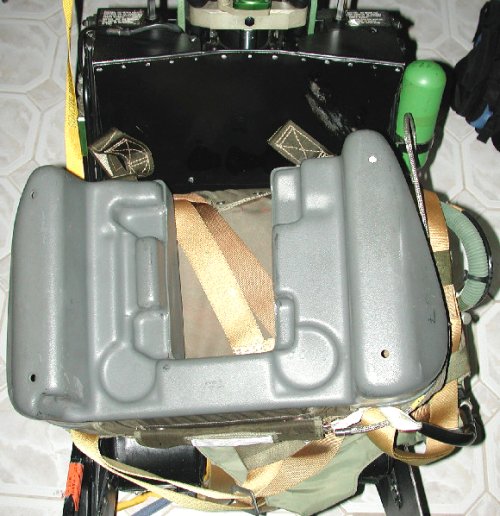
The parachute box lying on the seat bucket to show the
shape of the rear section. |
|
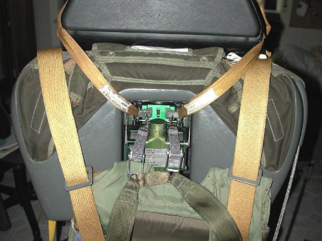
Parachute box front The inertia reel is visible, as
are the pack retaining bands. The seat mechanical release has been actuated and the
inertia reel straps have slipped out of the slot in the center where they normally lock. |
|
Headrest from left The DGU, Top Latch, Guillitine, and
parachute withdrawal line are nicely shown |
|
Headrest from right The upper half of the TRM is visible
behind the parachute pack. The pack retaining band is quite evident
as is the red/silver pin safing the face curtain actuating linkage at the top |
|
Top of headrest With the scissor shackle raised, the
drogue shackle and its connection to the drogue are quite visible. The red pins for
the main catapult sear, and the face curtain linkage are visible. |
|
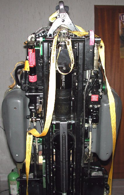
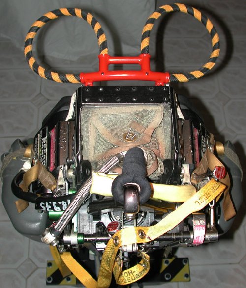
Seat without Parachute pack The green inertia reel unit
is visible in the center between the main beams. The circular pads just under the
headrest are for springs which force the parachute box off at seat separation. To the left of the
picture, the TRM rods are visible fully retracted. The square steel rods visible under the
triangular green fittings are the torque rods which are actuated by the TRM and will unlatch the leg
restraints, seat belt, and survival kit at seat separation. |
|

 These photos of Mark Schimmer's GQ-7A show it to be a different version from the one shown on this page. Among the differences are the color of the main parachute box, and the headrest shape. These pictures clearly show the shape of the parachute box which wraps around the main beam assembly to flatten the side of the seat. The yellow tape running around the seat is the flag which connects all the safing pins installed on the seat.