|
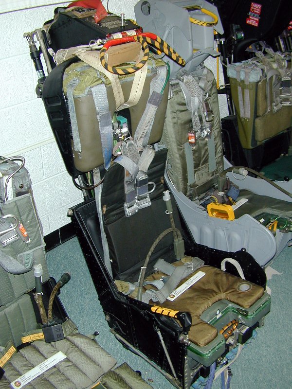
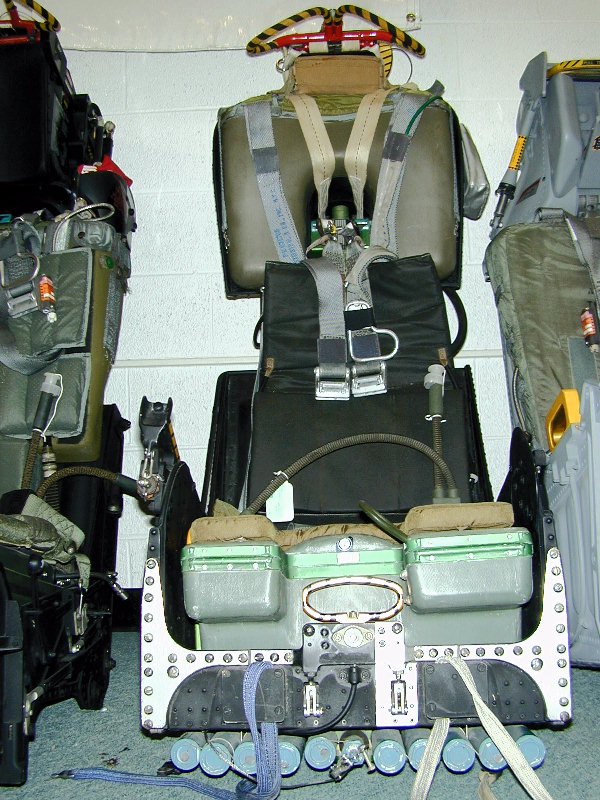
| The F-8 Crusader was equipped with the Martin-Baker Aircraft Mk. F-5 ejection seat, which was later updated to the Mk. F-7 standard. These photos from my friend Chris Woodul show his restored F-7 version. The major difference between the F-5 and the F-7 is the addition of the underseat rocket to give the seat zero-zero capability. Another change was the parachute pack from the soft pack to the hard pack variety seen held in the metal frame on the seat. The similar Mk. H-7 from the F-4 Phantom II utilized almost the same hard pack. The seat pan differs as well. Canopy breakers were added to the headrest to increase performance on ejection thru-canopy. |
The picture below clearly shows some
features common to the Mk. 5 and early Mk. 7 series seats such as the pack retention straps
which are made of cotton strapping, and the main parachute withdrawal line which is routed through
the guillitine(yellow covered unit.) For more explanation on how these systems work, check out
the Martin-Baker Ejection Details page.
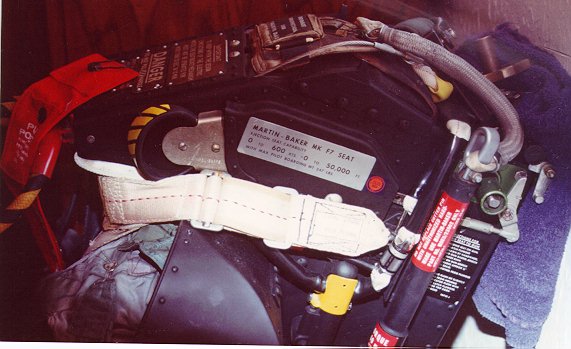
 This next shot shows also the drogue gun (tall red-labeled cylinder near the rear)and its
associated yellow trip-rod. The green anodized cylinder at the top right of the photo is the
top latch mechanism. This is where the crew is supposed to check and make sure the seat is installed
correctly. See the aforementioned page for an explanation.
This next shot shows also the drogue gun (tall red-labeled cylinder near the rear)and its
associated yellow trip-rod. The green anodized cylinder at the top right of the photo is the
top latch mechanism. This is where the crew is supposed to check and make sure the seat is installed
correctly. See the aforementioned page for an explanation.
The green sloted item near the middle of the seat is the seat pan guides which the pan rides up
and down on to adjust the crewmembers eye-line in the aircraft. Toward the front of this, part of the
guillitine gas manifold is also made of green anodized metal. The aluminized fabric pouch
is where the seat safety pins are stowed in flight.
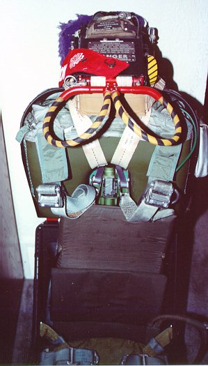 This photo shows the top of the seat to advantage. The double loop handles are the primary
initiation handles with the associated face curtain. The second yellow and black striped control
to the left side of the headrest (on the right of the photo) is the manual override for the
canopy interdictor. On the F-8, if the canopy did not jettison, the pilot could opt to pull this
handle, which would fire the seat thru the transparancy. The face curtain would have to be pulled
first, then the canopy override. This was not possible on the F-4 Phantom due to the metal frame
of the canopy being in the path of the seat.
This photo shows the top of the seat to advantage. The double loop handles are the primary
initiation handles with the associated face curtain. The second yellow and black striped control
to the left side of the headrest (on the right of the photo) is the manual override for the
canopy interdictor. On the F-8, if the canopy did not jettison, the pilot could opt to pull this
handle, which would fire the seat thru the transparancy. The face curtain would have to be pulled
first, then the canopy override. This was not possible on the F-4 Phantom due to the metal frame
of the canopy being in the path of the seat.
 This view shows the seat pan front area to good effect, showing the secondary firing handle, the leg
restraint lines and their snubbers, and in particular, the front of the inert underseat rocket.
Live rockets are normally painted white, with inert ones painted either completely blue, or at the
very least clearly marked INERT. The initiator is visible in the center of the row of rocket tubes
with its lanyard leading off to the left. Also shown in this photo is the initiator attached to the
manual override handle on the right side of the seat pan (left in photo). The handle pulls the sear out
of the initiator directly below it which sends hot gas to the guillitine mechanism on the upper left of
the main beam assembly to cut the parachute withdrawal line. The 'U' shaped piece of metal there is
the connection between the handle and the sear. Click on the picture for a slightly larger view.
This view shows the seat pan front area to good effect, showing the secondary firing handle, the leg
restraint lines and their snubbers, and in particular, the front of the inert underseat rocket.
Live rockets are normally painted white, with inert ones painted either completely blue, or at the
very least clearly marked INERT. The initiator is visible in the center of the row of rocket tubes
with its lanyard leading off to the left. Also shown in this photo is the initiator attached to the
manual override handle on the right side of the seat pan (left in photo). The handle pulls the sear out
of the initiator directly below it which sends hot gas to the guillitine mechanism on the upper left of
the main beam assembly to cut the parachute withdrawal line. The 'U' shaped piece of metal there is
the connection between the handle and the sear. Click on the picture for a slightly larger view.
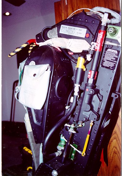
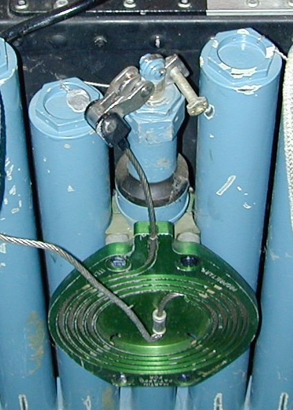 This photo shows the same seat tilted back to show the rocket pack and its initiator lanyard
tray. The lanyard is stowed in a spiral tray under the rocket and
is attached to the cockpit floor. Some six feet of travel of the seat
unspools the lanyard, which then withdraws the sear and fires the rocket. On this seat, the
clip end which attaches to the cockpit floor has been drawn up across the front of the rocket
tubes and clipped out of the way for handling. This is proper procedure on a live seat as well.
The block attached to the sear is attached to the outer edge of the spiral lanyard. When the seat
travels up the rails, the cable uncoils, and at full stretch withdraws the sear (click
here for a closeup of the lanyard and sear.) On this seat, a
bolt has been placed through the safety pin hole in the sear to prevent accidental removal. On the
removal of the sear, the firing pin would fall onto the percussion primer of the initator cartridge.
This would send hot gas through the initiator tube to the manifold at the rear of the seat. This
manifold has attached to it the ten tubes of rocket propellant, four nozzles, and the initiator tube as well as a mechanical attitude adjustment lever. The hot gas pressurizes the manifold and ignites the ten tubes of propellant. Once the pressure reaches optimum, steel disks which seal the exhaust
nozzles are forced out and the rocket provides thrust. The rocket thrust is aimed through the expected center of gravity of the seat/man mass. This is adjusted for smaller or larger crewmen by
the mechanical attitude adjustment lever (not shown). This interfaces with a slot on the main beam
assembly, and when the seat bucket is adjusted up or down, the lever forces the rocket pack to pivot
on the two attachment points on either side of the manifold. This aligns the rocket for the best-fit
alignment for a person of a specified torso height.
This photo shows the same seat tilted back to show the rocket pack and its initiator lanyard
tray. The lanyard is stowed in a spiral tray under the rocket and
is attached to the cockpit floor. Some six feet of travel of the seat
unspools the lanyard, which then withdraws the sear and fires the rocket. On this seat, the
clip end which attaches to the cockpit floor has been drawn up across the front of the rocket
tubes and clipped out of the way for handling. This is proper procedure on a live seat as well.
The block attached to the sear is attached to the outer edge of the spiral lanyard. When the seat
travels up the rails, the cable uncoils, and at full stretch withdraws the sear (click
here for a closeup of the lanyard and sear.) On this seat, a
bolt has been placed through the safety pin hole in the sear to prevent accidental removal. On the
removal of the sear, the firing pin would fall onto the percussion primer of the initator cartridge.
This would send hot gas through the initiator tube to the manifold at the rear of the seat. This
manifold has attached to it the ten tubes of rocket propellant, four nozzles, and the initiator tube as well as a mechanical attitude adjustment lever. The hot gas pressurizes the manifold and ignites the ten tubes of propellant. Once the pressure reaches optimum, steel disks which seal the exhaust
nozzles are forced out and the rocket provides thrust. The rocket thrust is aimed through the expected center of gravity of the seat/man mass. This is adjusted for smaller or larger crewmen by
the mechanical attitude adjustment lever (not shown). This interfaces with a slot on the main beam
assembly, and when the seat bucket is adjusted up or down, the lever forces the rocket pack to pivot
on the two attachment points on either side of the manifold. This aligns the rocket for the best-fit
alignment for a person of a specified torso height.
| The Ejection Site Home | |
|---|---|
| Send email to Kevin |