The Ejection Site
F/A-18 Martin-Baker SJU-5/6A Seat
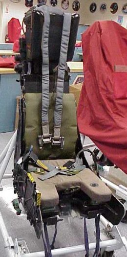 The seat shown here is a Martin-Baker Mk. 10US seat as fitted to the F/A-18. Many
F/A-18s are also equipped with the SJU-17 NACES seat. In this case, the SJU-5/6A is the
older style seat, but still a very good seat. The Mk. 10 is also used in many other aircraft
including the Tornado IDS, and the
Alpha Jet. The SJU-5/6A is also commonly used in experimental
aircraft at NASA's Dryden Flight Research Center, where these photos are from.
The seat shown here is a Martin-Baker Mk. 10US seat as fitted to the F/A-18. Many
F/A-18s are also equipped with the SJU-17 NACES seat. In this case, the SJU-5/6A is the
older style seat, but still a very good seat. The Mk. 10 is also used in many other aircraft
including the Tornado IDS, and the
Alpha Jet. The SJU-5/6A is also commonly used in experimental
aircraft at NASA's Dryden Flight Research Center, where these photos are from.
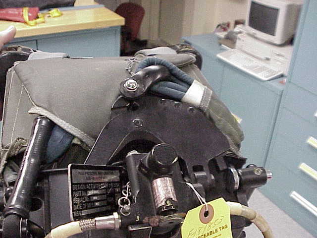
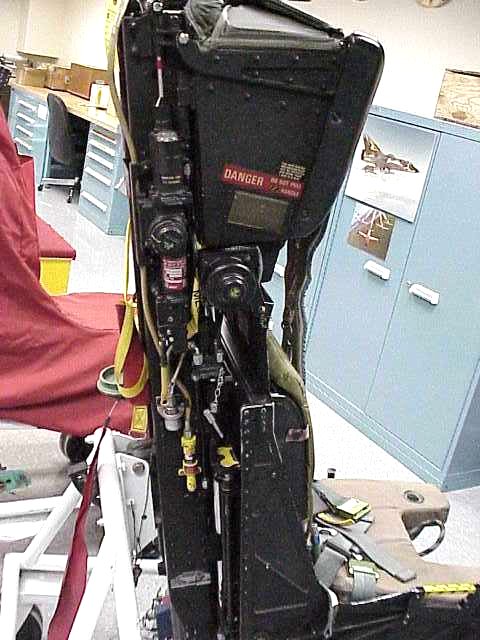
The
Timer Release Mechanism is very similar to the type used in
the earlier versions of the Martin-Baker seats such as the Mk. H-7 seat used in the
F-4 Phantom II. The main difference is in the way the TRM releases
the scissors shackle. This photo of the headrest shows
that the parachute box headrest has been placed on the seat, but not connected. The drogue
shackle is visible with the blue nylon loop near, but not in, the scissors shackle connection
in the center of the photo.
The scissor shackle is somewhat different from prior versions as well. The dual gas lines to
the catapult initiator are visible at the base of the picture. The catapult initiator is
between the legs of the scissor shackle. The TRM connection is on the right hand side of
the picture.
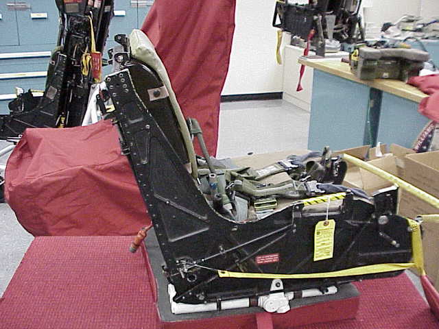
Since the parachute is not fully rigged, this picture
shows the inertia reel strap fittings on the risers hanging loose. The SEWARS salt-water actuated
releases on the Koch fittings are clearly visible. The SEWARS units are a prime part of the
survival gear. In case of a water landing, the SEWARS would disengage the parachute risers by
shattering the crosspiece under the nylon. This allows the parachute to drift away from the
crewman and hopefully prevent it from either dragging the crewman or landing on the crewman
and making it difficult for him/her to keep his/her head out of the water. The hook/loop
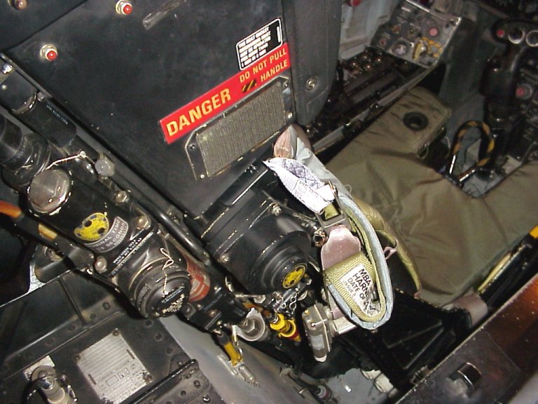
fastener pads near the Koch fittings are used to hold the risers against the side of the
headrest on the hook part of the pads which can be seen here
just under the red "DANGER DO NOT PULL /// HANDLE". This is to allow the crew to
enter the cockpit and strap in easier. Once seated in the cockpit, the leg restraints and risers
would be connected as soon as possible to allow for a ground ejection in case of a problem on the
flight line. Just under the headrest is the inertia reel unit, which unlike previous Martin-Baker
systems is wider and mounted in front of the main beam assembly. Also visible is the composite
back section which the padding is attached to. Nearer the top, the Drogue Gun Unit is visible,
as well as the top latch wheel (golden star shaped unit) which is used to unlatch the
seat from the catapult and allow the seat to be removed for maintainance.
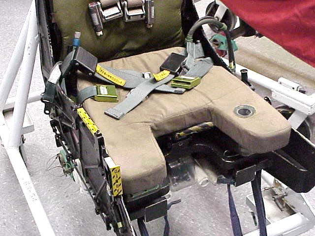
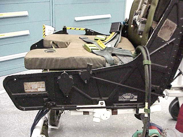
The seat bucket contains most of the controls on the SJU-5/6A as well as the survival kit with the
internal emergency oxygen system. As seen in this view,
the seat safety control is at the front right of the bucket. The control is in the safe position.
When it is tilted back into the armed position, the ARMED label would be visible to the
crewman. Directly behind that is the manual separation handle (sometimes called the scramble
handle). This is used to separate from the seat if there is a believe that the seat mechanisms
had failed. Centrally located on the front of the bucket is the ejection initiation handle.
This loop shaped handle is tilted forward in this photo so the top of the yellow and black
stripes are visible. The clear plastic under it is the cover for the initiators. On the left
thigh area there is a visible hole in the padding which is used to see the oxygen bottle guage
in the survival kit. The hoses at the rear of the kit are for the emergency oxygen (right side
of the kit {left in this picture}), and the REDAR hose and communications connection on the left
side.
The leg restraint line snubber boxes are visible under the front protrusions of the survival
kit. The blue nylon lines hanging down from the seat are attached at one end to the cockpit floor
and fed through the snubbers then through the crewman's garters, and back to the snubber unit.
On ejection, the lines are puilled throught the snubbers to hold the crewman's legs against the
front of the bucket. The floor attach points have shear pins on them so that when the legs are
in fully back, the lines are released from the cockpit. On seat separation, the snubbers are
mechanically released.
The straps are the lap belt to the rear with the
black adjusting boxes, and the survival kit straps with the green connectors forward of that.
The green boxes connect to the crewman's harness at the hip. After seat separation, these
straps hold the survival kit to the crewman as he/she decends under the parachute. These
fittings are more typical of the USAF type seats. This seat from NASA is being modified to
the NASA standard which uses the USAF PCU-15/P or PCU-16/P
parachute harness with the F-16 ACES II type
Frost riser connections on all their normal seats. This allows the crewman to use a single
harness for several different type of aircraft. The riser fittings have not
been changed yet on this seat.
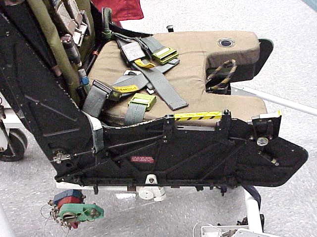
On the
other side of the bucket, the guarded switch raises or
lowers the seat bucket on hte main beams for proper position in the cockpit. The mechanical
lever just aft of that is used to lock or release the inertia reel straps, which like the
shoulder belt in an automobile allow for leaning forward, but will lock under a decelleration
load. The aircraft units also can be manually locked with this control. The inertia reel
unit is visible just under the headrest in this picture.
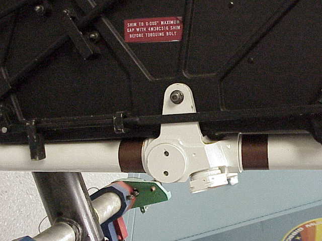
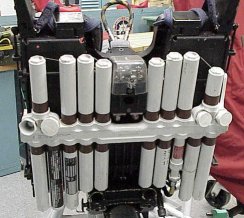 Mounted below the seat bucket is the underseat rocket. Consisting of seventeen rocket
proppellant tubes connected to a manifold which also has four nozzles and an initiator tube.
In the accompianing photo, three of the nozzles are protected by ground safety caps. The one
on the left of the photo is uncovered showing the press fit disk inside of the nozzle. As the
pressure from the rocket tubes builds after initiation, these disks are forced out allowing
the rocket exhaust to boost the seat clear of the aircraft.
Mounted below the seat bucket is the underseat rocket. Consisting of seventeen rocket
proppellant tubes connected to a manifold which also has four nozzles and an initiator tube.
In the accompianing photo, three of the nozzles are protected by ground safety caps. The one
on the left of the photo is uncovered showing the press fit disk inside of the nozzle. As the
pressure from the rocket tubes builds after initiation, these disks are forced out allowing
the rocket exhaust to boost the seat clear of the aircraft.
Thanks to Nick Kiriokos for providing these photos.

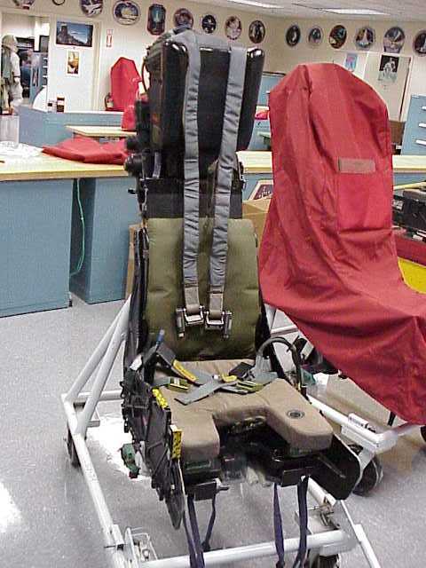 The seat shown here is a Martin-Baker Mk. 10US seat as fitted to the F/A-18. Many
F/A-18s are also equipped with the SJU-17 NACES seat. In this case, the SJU-5/6A is the
older style seat, but still a very good seat. The Mk. 10 is also used in many other aircraft
including the Tornado IDS, and the
Alpha Jet. The SJU-5/6A is also commonly used in experimental
aircraft at NASA's Dryden Flight Research Center, where these photos are from.
The seat shown here is a Martin-Baker Mk. 10US seat as fitted to the F/A-18. Many
F/A-18s are also equipped with the SJU-17 NACES seat. In this case, the SJU-5/6A is the
older style seat, but still a very good seat. The Mk. 10 is also used in many other aircraft
including the Tornado IDS, and the
Alpha Jet. The SJU-5/6A is also commonly used in experimental
aircraft at NASA's Dryden Flight Research Center, where these photos are from.
